
Inside an Injectable-Vial Production Line: Washing, Filling and Capping
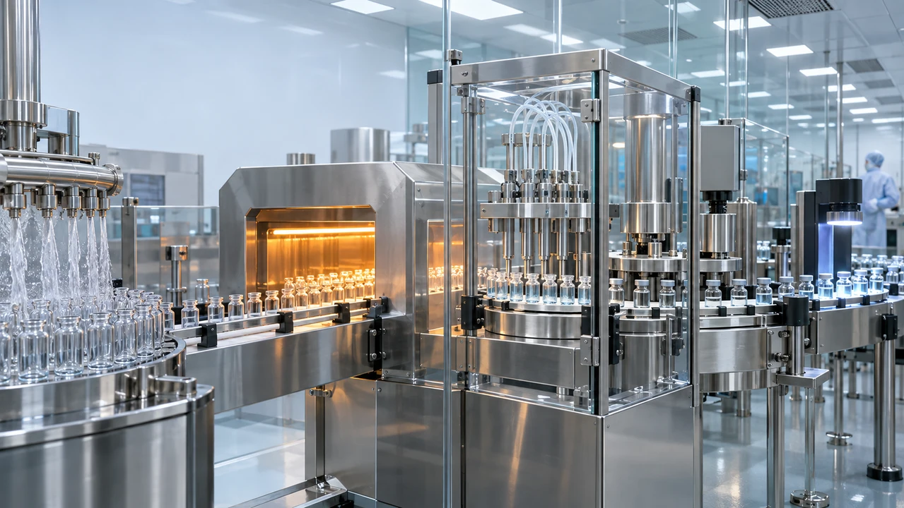
Injectable medicines demand one of the most tightly controlled manufacturing environments in healthcare. A vial that appears simple at the point of use has passed through a coordinated system of equipment, utilities, environmental controls, trained personnel, quality procedures, and documented testing.
A typical injectable-vial production line moves containers through seven principal stages:
-
Vial preparation and washing
-
Dry-heat depyrogenation
-
Transfer into the aseptic processing zone
-
Filling
-
Stoppering
-
Capping or crimping
-
Inspection, testing, and batch disposition
The exact configuration depends on the drug product, container size, production capacity, sterilization strategy, and applicable regulatory requirements. A liquid injectable, lyophilized product, potent compound, biologic, and clinical-trial batch may each require a different equipment and containment strategy.
1. Vial Infeed and Preparation
The process begins with empty pharmaceutical-grade vials. They may arrive in bulk trays or other validated packaging and are introduced to the line through an infeed table or automated handling system.
Before equipment is selected, the manufacturer must define the intended container range. Important factors include:
-
Vial material and format
-
Nominal fill volume
-
Neck and finish dimensions
-
Container tolerances
-
Required line speed
-
Change-part requirements
-
Resistance to thermal processing
-
Compatibility with stoppers and caps
Consistent container geometry matters because every downstream operation—washing, conveying, filling, stoppering, capping, and inspection—depends on repeatable positioning. Poorly matched components can contribute to broken glass, line stoppages, cosmetic defects, incomplete seals, or rejected units.
Format flexibility should also be considered early. A line designed around only one vial size may have a lower initial cost, but a multi-format line can provide greater long-term production flexibility when supported by validated changeover procedures.
2. Automated Vial Washing
The vial washer removes loose particles, residues, and other contaminants from the internal and external surfaces of each container. Depending on the equipment design, vials may pass through several washing stations using recirculated water, purified water, Water for Injection, filtered compressed air, or another validated sequence.
A common process moves vials through progressively cleaner rinsing stages. Final rinses typically receive the highest level of control. Internal cleaning is especially important because the product will later contact the same glass surface.
Critical washer considerations include:
-
Water quality and microbial control
-
Rinse sequence and contact time
-
Spray-needle alignment
-
Water pressure and flow
-
Compressed-gas quality
-
Drainage and prevention of recontamination
-
Broken-vial detection
-
Cleaning and changeover accessibility
-
Repeatability across the full operating speed range
The objective is not merely to make a vial look clean. The washing cycle must be developed, controlled, and documented as part of the overall contamination-control strategy.
3. The Depyrogenation Tunnel
After washing, vials commonly enter a continuous dry-heat depyrogenation tunnel. This stage is sometimes described simply as “sterilization,” but the distinction is important: the tunnel is designed not only to deliver a validated lethality process, but also to reduce pyrogenic contamination—particularly bacterial endotoxins—to an established level.
The tunnel generally includes three functional zones:
-
Preheating zone: Raises the temperature of washed vials in a controlled manner.
-
High-temperature zone: Exposes the containers to the validated dry-heat cycle.
-
Cooling zone: Reduces container temperature while maintaining controlled, highly filtered airflow.
The process must balance time, temperature, airflow, belt speed, heat distribution, and container loading. Those parameters are evaluated through qualification studies, including temperature mapping and biological or endotoxin challenge studies when appropriate to the validation strategy.
High-efficiency filtered airflow helps maintain environmental control as the vials move toward the filling area. The transition from the tunnel into the aseptic zone is particularly important because the containers must remain protected after the validated heat process.
Key tunnel considerations include:
-
Temperature uniformity
-
Belt-speed control
-
Heat penetration
-
Endotoxin-reduction target
-
HEPA-filter integrity
-
Differential pressure
-
Airflow visualization
-
Cooling performance
-
Alarm and interlock functions
-
Data recording and audit trails
4. Transfer into the Aseptic Filling Zone
Depyrogenated vials emerge into a critical processing area where environmental and operator controls become central to product protection. Depending on the facility and process, the line may use restricted-access barrier systems, isolators, or another qualified cleanroom arrangement.
Barrier technology can reduce direct operator interaction with exposed sterile containers and product-contact operations. However, automation does not eliminate the need for sound aseptic practices. Glove systems, transfer ports, interventions, environmental monitoring, cleaning, disinfection, and line setup all require defined and validated procedures.
The line should be designed to minimize unnecessary movement, open-container exposure, difficult-to-clean surfaces, and operator interventions. Routine and non-routine interventions should be identified in advance and represented appropriately during aseptic process simulations.
5. Aseptic Filling
At the filling machine, a precisely controlled quantity of product is dispensed into each vial. Filling technology may use peristaltic pumps, piston pumps, time-pressure systems, rotary-piston systems, or other product-appropriate methods.
No single filling technology is ideal for every application. Selection depends on factors such as:
-
Product viscosity
-
Required dose accuracy
-
Sensitivity to shear or foaming
-
Product-contact materials
-
Batch size
-
Filling speed
-
Cleaning strategy
-
Single-use versus reusable flow paths
-
Potency and containment requirements
-
Acceptable product loss
The filling system must consistently deliver the specified volume while protecting product quality and sterility. In-process controls may include weight checks, fill-volume verification, no-vial/no-fill logic, container-position detection, and automatic rejection of nonconforming units.
Product-contact components must be sterilized or supplied in a qualified sterile state. Their assembly, connection, storage, and maximum allowable hold times should be defined. Where nitrogen purging or another inert-gas step is required, gas quality, pressure, flow, and product compatibility must also be controlled.
6. Stoppering
Immediately after filling, each vial receives an elastomeric stopper. For a conventional liquid product, the stopper is normally seated fully before the vial leaves the protected filling environment.
Lyophilized products follow a different path. The stopper may initially be placed in a partially seated position so water vapor can escape during freeze-drying. After the lyophilization cycle, the stopper is fully seated within the lyophilizer before the vials proceed to capping.
Stoppering performance depends on more than mechanical placement. The stopper formulation, dimensions, surface treatment, washing process, sterilization cycle, feeding system, and compatibility with the drug product and vial all matter.
Equipment controls commonly monitor:
-
Stopper presence and orientation
-
Placement depth
-
Vial position
-
Feed-bowl operation
-
Stopper-track conditions
-
Jam detection
-
Reject handling
Container-closure integrity begins with a properly selected and correctly seated stopper, but it is ultimately established through a validated system that includes the vial, stopper, cap, capping process, storage conditions, and test method.
7. Capping and Crimping
The cap secures the stopper to the vial and helps preserve the integrity of the container-closure system. A typical closure includes an aluminum crimp seal and a plastic flip-off component.
During capping, the machine applies controlled downward and rotational forces to form the aluminum skirt beneath the vial finish. Too little force may produce a loose seal. Excessive force can deform components, damage the stopper, create particles, or break the vial.
Important capping controls include:
-
Cap presence and orientation
-
Crimp dimensions
-
Capping force or head settings
-
Vial-height and component tolerances
-
Cosmetic appearance
-
Particle control
-
Detection and rejection of missing or defective closures
Capping equipment must be positioned and controlled so that the closure process does not compromise an otherwise acceptable aseptic operation. The contamination-control strategy should address how stoppered vials are protected until the cap has been properly applied.
8. Inspection and Reject Management
Every finished vial must be evaluated against established acceptance criteria. Inspection systems may be manual, semi-automated, or fully automated, depending on the product, batch size, risk profile, and manufacturing strategy.
Inspection can identify defects such as:
-
Visible particles
-
Incorrect fill level
-
Cosmetic glass defects
-
Cracks or breakage
-
Missing or displaced stoppers
-
Missing or malformed caps
-
Improper crimps
-
Product discoloration or turbidity
-
Container leaks or closure anomalies
Automated systems may combine high-speed cameras, controlled lighting, container rotation, and software-based defect detection. These systems still require qualification using representative defect sets and an established inspection standard. Manual inspection likewise requires controlled conditions, trained inspectors, and periodic qualification.
Rejected units should be positively segregated and reconciled. Reject data can also serve as a process-monitoring signal: a rising defect rate may indicate equipment wear, component variation, an upstream process shift, or an emerging maintenance issue.
9. Qualification and Validation
An injectable-vial line is not ready for routine use merely because the machines operate. The equipment, utilities, control systems, cleanroom, process, and supporting procedures must work together and produce documented evidence of consistent performance.
A typical lifecycle includes:
User Requirements Specification
The User Requirements Specification, or URS, defines what the system must do. It can address capacity, vial formats, product characteristics, cleanroom interfaces, utilities, automation, alarms, recipes, electronic records, cleaning, containment, documentation, and applicable standards.
Design Qualification
Design Qualification evaluates whether the proposed design is suitable for the intended process and approved requirements. Design reviews should occur before fabrication decisions become expensive to change.
Factory Acceptance Testing
Factory Acceptance Testing, or FAT, is performed at the equipment manufacturer’s facility. It provides an opportunity to verify major functions, documentation, controls, safety features, format handling, and agreed test criteria before shipment.
Site Acceptance Testing
After installation, Site Acceptance Testing, or SAT, confirms that the delivered system is complete, correctly assembled, and capable of operating in its installed environment.
Installation and Operational Qualification
Installation Qualification documents that equipment and supporting systems were installed as approved. Operational Qualification challenges functions, operating ranges, alarms, interlocks, sequences, and controls under defined conditions.
Performance Qualification and Process Validation
Performance Qualification evaluates operation under representative conditions. Process validation then provides documented evidence that the integrated manufacturing process can perform effectively and reproducibly. FDA’s process-validation framework emphasizes a lifecycle approach: process design, process qualification, and continued process verification.
For aseptic processing, qualification also extends to cleanrooms, HVAC systems, HEPA filters, water systems, compressed gases, sterilization processes, cleaning and disinfection, personnel practices, environmental monitoring, and aseptic process simulations—commonly called media fills.
10. Integration Is the Real Engineering Challenge
The individual machines are only part of the project. A reliable line depends on successful integration across the full system:
-
Mechanical transfer between machines
-
Accumulation and line balancing
-
Cleanroom and barrier interfaces
-
HVAC and pressure cascades
-
Water, steam, gases, vacuum, and power
-
Supervisory control and data collection
-
Recipe and user-access management
-
Electronic records and audit trails
-
Cleaning and sterilization strategy
-
Component and personnel flows
-
Maintenance access
-
Spare-parts planning
-
Training and technical support
A line rated for a particular maximum speed will not necessarily achieve that output in routine production. Actual capacity can be constrained by container handling, interventions, fill characteristics, inspection performance, changeovers, cleaning, environmental monitoring, or the slowest integrated machine.
For this reason, buyers should distinguish between nominal machine speed and demonstrated, sustainable line output under defined operating conditions.
Questions to Ask Before Purchasing a Vial Line
Before selecting equipment, the project team should be able to answer the following:
-
What products, vial sizes, stopper formats, and cap formats will the line handle?
-
Is the process liquid filling, lyophilization, or both?
-
What batch sizes and sustained production rates are required?
-
Which markets and regulatory expectations will the facility serve?
-
What barrier technology and cleanroom classification strategy will be used?
-
Which utilities are available, and at what capacity and quality?
-
How will cleaning, sterilization, and product changeover be performed?
-
What level of automation, electronic records, and audit-trail functionality is required?
-
What FAT, SAT, commissioning, qualification, and validation support is included?
-
What spare parts, training, warranty, and post-installation service will be available?
Conclusion
An injectable-vial production line is a coordinated contamination-control and quality system—not simply a row of machines. Washing prepares the container. The dry-heat tunnel depyrogenates it. Aseptic filling introduces the sterile product under controlled conditions. Stoppering and capping establish the closure system. Inspection identifies visible defects, while qualification and validation demonstrate that the complete process can operate consistently.
The most successful projects begin with a precise URS, a realistic capacity model, early attention to utilities and facility interfaces, and a lifecycle plan for qualification, maintenance, and continuous process verification.
Truway Health works with healthcare and institutional stakeholders evaluating medical, laboratory, and pharmaceutical equipment. Project requirements should always be reviewed by qualified engineering, quality, regulatory, validation, and clinical professionals before equipment is selected or placed into regulated production.
References and Further Reading
-
U.S. Food and Drug Administration, Sterile Drug Products Produced by Aseptic Processing—Current Good Manufacturing Practice
-
U.S. Food and Drug Administration, Process Validation: General Principles and Practices
-
European Commission, EU GMP Annex 1: Manufacture of Sterile Medicinal Products
This article is provided for general educational purposes and does not constitute regulatory, validation, engineering, medical, or legal advice. Facility- and product-specific requirements must be established by the responsible manufacturer and appropriately qualified professionals.
Truway Health News & Insights

Healthcare Equipment Interoperability: Understanding DICOM, HL7, and FHIR
Truway Health | Medical Technology, Digital Infrastructure & Healthcare Innovation Modern medical eq...

Medical-Grade Stainless Steel: Comparing 304 and 316 for Healthcare Equipment
Truway Health | Medical Equipment, Materials Engineering & Healthcare Procurement Not all stainless...

Winter Respiratory Season Preparedness: Essential Supplies for Caregivers and Clinics
Published October 18, 2026 | Truway Health News & Insights When respiratory illnesses rise, preparat...

What Families Should Know When a Loved One Enters Hospice Care
For families with a terminally ill loved one, the start of hospice can land like two realities at on...

Moving from RN to Family Nurse Practitioner What You Need to Know
Experienced registered nurses often reach a point where strong bedside skills still leave a lingerin...

The Guidewire Is Not a Commodity: The Hidden Safety Architecture of Coronary Care
How precision engineering, clinical intelligence, and medical-device traceability are redefining exp...